Turning pins are a method of attaching components of armour to one another, first showing up in the 15th century (often for greaves) and later used in exchange armours. An example can be found on Wade Allen’s website for the A155 (picture and link to site below). These became more common in “Garnitures” as harnesses were built to have exchange pieces to customize them for specific purposes, including specific types of tournament.

This is the first half of a 2-part article: this part is how to make the turning pin, which is symmetric, rather than a turning hook as seen above. The second part (which I will link once it is complete) is how to install a turning pin (and associated locking rivet) and how these are used to attach armour together on an exchange piece (an arm harness) to allow the use of either a spaulder or a full pauldron.
Materials and equipment
The only material needed is a section of 5/16″ bar stock. manufacture of turning pins is trivial if you have a lathe, but I demonstrate the use of an angle grinder, file and drill press. My full equipment list is as follows:
- safety gear (ear protection, gloves, face shield…)
- Heat Source (Oxy-Acetylene welder using an Oxy-propane mix)
- Anvil-shaped-object (I used my stake plate, since it was convenient)
- A shaping hammer (I used a 2 pound / 1 kg hammer with a slightly domed face)
- Bench Vice
- Hacksaw with metal blade
- Cordless drill
- Angle grinder with 1/16″ cutoff wheel
- Drill Press
- files (Bastard file with safe edge, mill file)
- Autobody sander with 240 and 320 grit sanding disks
TL:DR
The quick overview is that you need to smash the end of the rod so that it is a bit over 1/8″ thick, then turn the shaft down so that it will fit though an appropriate rivet hole. Since I use 9/64″ holes for most of my articulations this is the hole size I wanted to use for this purpose, which means that I turn the shaft so that it fits snugly (but not tightly) into this hole. You will then want to shape the outside of the “key” into a roughly semi-circular shape and clean up the visible sides and edges. I use a cordless drill to keep my piece spinning while I cut the shaft down on an angle grinder. Once I have shaped the shaft between 3/16″ and 1/8″ I move it to a drill press and use a file to do the fine shaping.
Detailed instructions
I’ll start by saying that my new methodology cleans up the sides of the “key” before shaping the shaft, since it’s way easier to do that when you have a “handle”. I now leave a bit more thickness and grind the thickness down to roughly 1/8″ when I do this clean up, with the “semicircle” shaping still happening just before I cut the turning pin off the sprue.
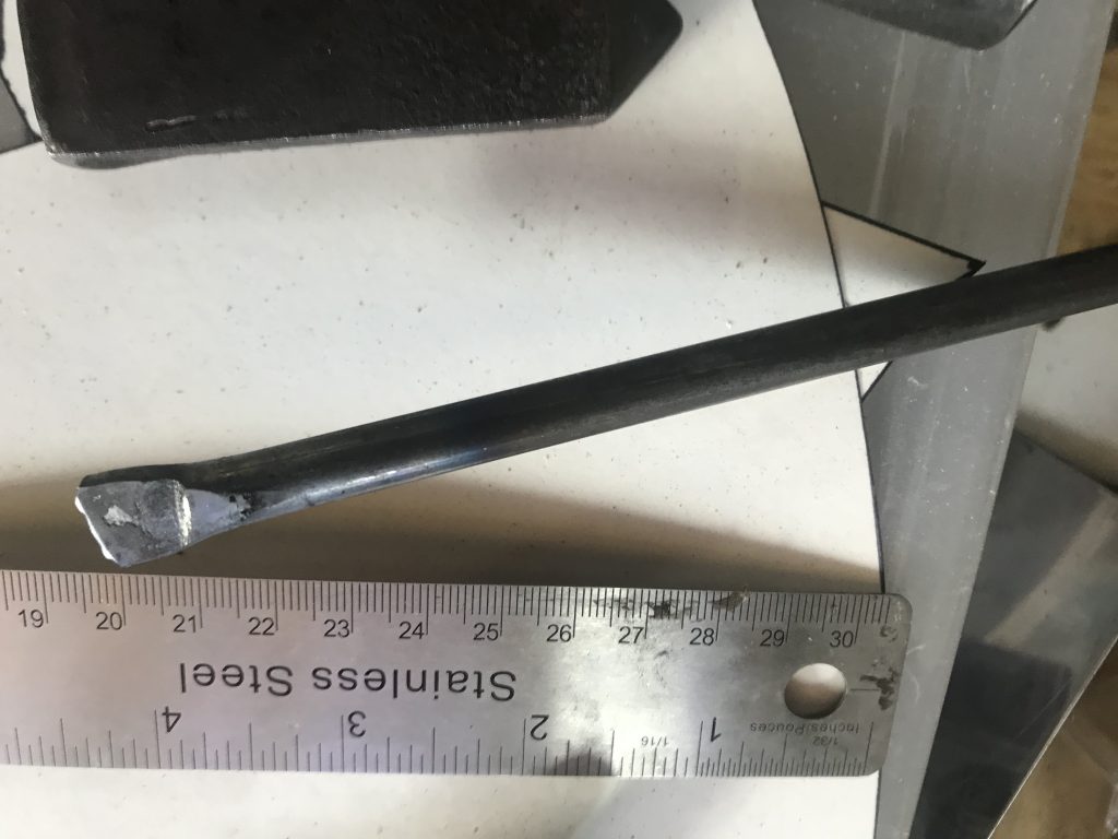
The first step is to upset the end of the rod. I strongly recommend using heat to do this since it is much easier and leads to less wear on your equipment – I attempted this without heat and decided that if I need to use a 4 pound (2 kg) hammer on a “detail” piece I am probably doing something wrong. As you can see in the picture below, you don’t need this to be particularly pretty, since almost all of the exposed metal will be ground away by the time this is finished.
Once the rod is upset, I place the (still round) other end of the rod into a drill, and make sure that this is spinning as I advance this into an angle grinder held in a bench vice. I use a 1/16″ cutoff wheel because I want to have as close as possible to a 90 degree cut. You will need to turn down around 1/4″ to 3/8″ of material to have enough length to pass through both plates and to have material to upset to hold the pin in place, much like an articulation rivet.
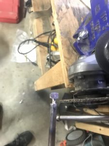
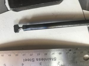
Once the rough turning is completed the pin is cut from the rest of the rod, ensuring that roughly 1/2″ of rod is preserved below the cut shaft so that there is enough for the jaws of the drill press to grip. Note that I now clean up the sides of the pin before I cut it from the rod, since that is much easier than doing it last in terms of handling and fine manipulation. Secure the pin in the jaws of the drill press and use a file to cut the shaft down to 1/8″.
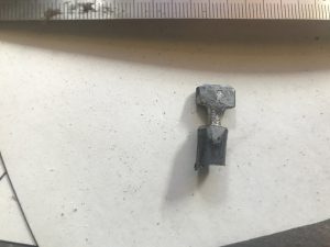
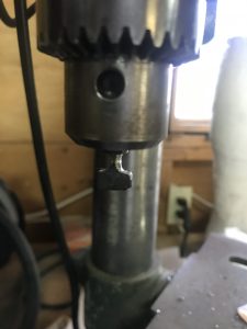
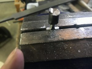
Once the pin is turned, I will clean up the “bottom” edge of the pin by clamping the pin in a vice. this will provide a solid (and symmetric) contact surface once the pin is installed. Note that trying to get this cleaned up in the drill press is “challenging” at best since there is nowhere for the file to “rest” as the “arms” of the turning pin turn unless you ensure that the flat portion of the pin is at least 3/16″ (and preferably thicker) at which point you will not have a lot of “grip” when you install the pin.
 >
>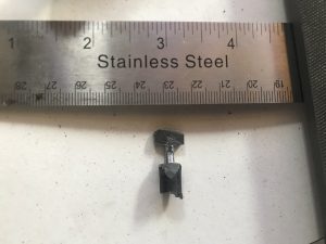
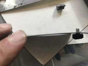
Once the pin is nicely symmetric (you can test this by putting it back in the drill press and spinning it) you can cut the shaft. Note that it is much easier to do the final shaping while it is still attached to the “sprue” that you turned it on. Once it is cut you can test fit it to the shaft size that you are planning to use to install. If needed (usually) you can mount this back in the vice and file to “round enough” to clear the hole. Your perfect fit is tight so that the pin will only fit in the hole by entering at 90 degrees to the plate, and is a bit stiff to turn. The second picture shows my test fitting, and the clearance between the outer plate edge and the pin can be forced to be flush, but binds when I force it – which is just about perfect in terms of function, since you do not want the pin turning once it is engaged and “locked”.
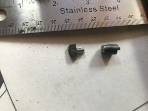
Here we have the finished turning pin, after I have curved the top into the traditional “half moon” shape on the top. The depth of this pin is somewhat subjective – many “turning hooks” are quite thin, while many pins (with overhang on both sides) are “chunkier” and (in my experience) range from about 1/4″ to 1/2″ or so. I personally aim for about 3/8″ since this is enough that I can engage the pin with gloves (or gauntlets) on, and is till thin enough that I am not cutting huge slots into my top plate to allow them to slide onto the pin. Note that because the plate needs to slide over the pin, the taller the pin the longer the slot needed to allow the pin to pass through it. This is also why there is a curved surface on the outside of the pin, since it helps “seat” the pin while it is being engaged, and reduces the slot requirement.
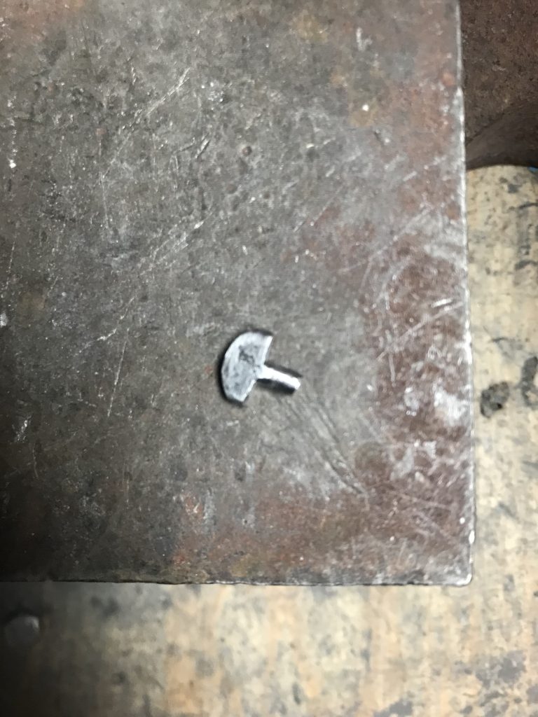
You can see that there is still scale embedded in the sides of the pin: I have ground these to a mirror finish, but every pin that I have seen in “real” armour has had this roughness on the sides of the pin, so I now leave these with the slightly uneven surface, for the same reason that I no longer cut my countersunk rivets to EXACTLY the plate depth to make them vanish – this more accurately reflects what real armour looks like.