STILL IN DRAFT – latest update March 31, 2020 (Pattern links added)
Pattern links: Word Format (11″ x 17″ tabloid size) or PDF format (11″ x 17″ tabloid size)
As part of the harness I am working on, I needed to construct a gorget. Most 15th century Milanese armour has a fairly large neck opening which is meant to accommodate a mail standard (mail neck defences) I would like to have the ability to use this as a combat harness, which means that I would like to have plate defences for my neck both from a “rules” point of view (because most armoured combat groups require rigid neck armour) and because I really like being able to use all of my limbs, and have taken a number of hits to my neck area which would have been concerning if I wasn’t generally armoured like a tank.
Wade Allen owns the nicest gorget I have handled (linked) so if I am going to use a non-period solution, I wanted to make the nicest one possible. Ironically, this type of armour could be seen as the ultimate development of milanese armour, since 17th century armour is very functional, with minimal fluting and integrates all of the components. To quote Wade and Mac (Robert Macpherson) “if you want to build a 17th century suit of armour, first build the gorget…”
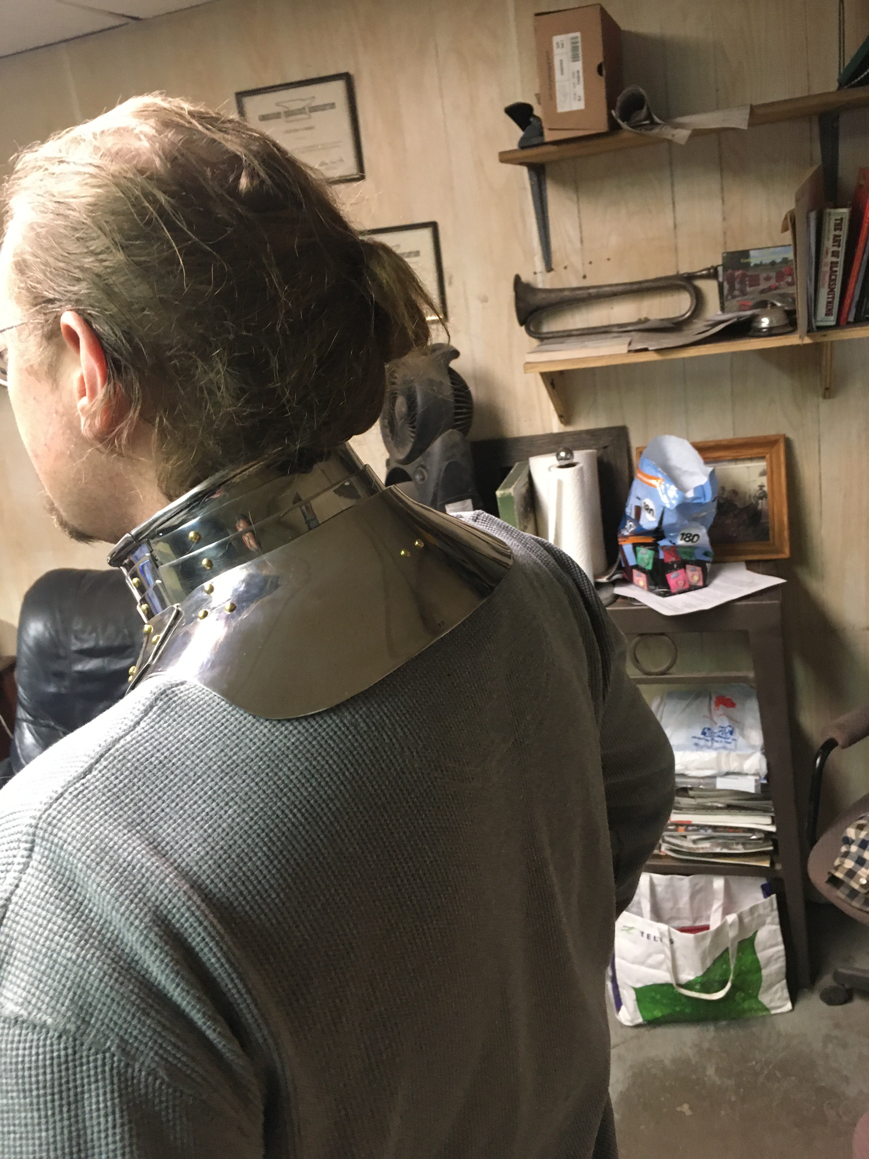
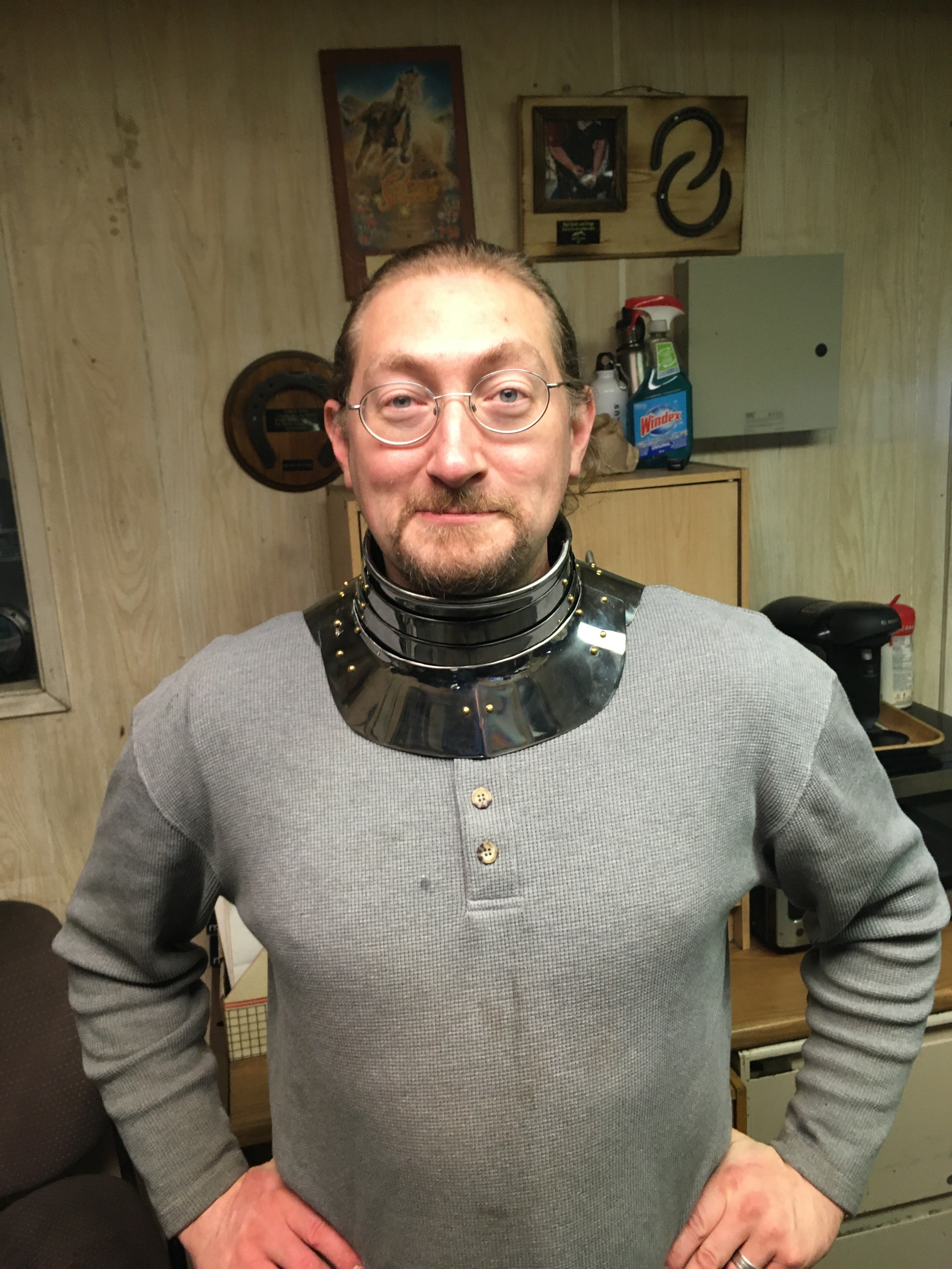
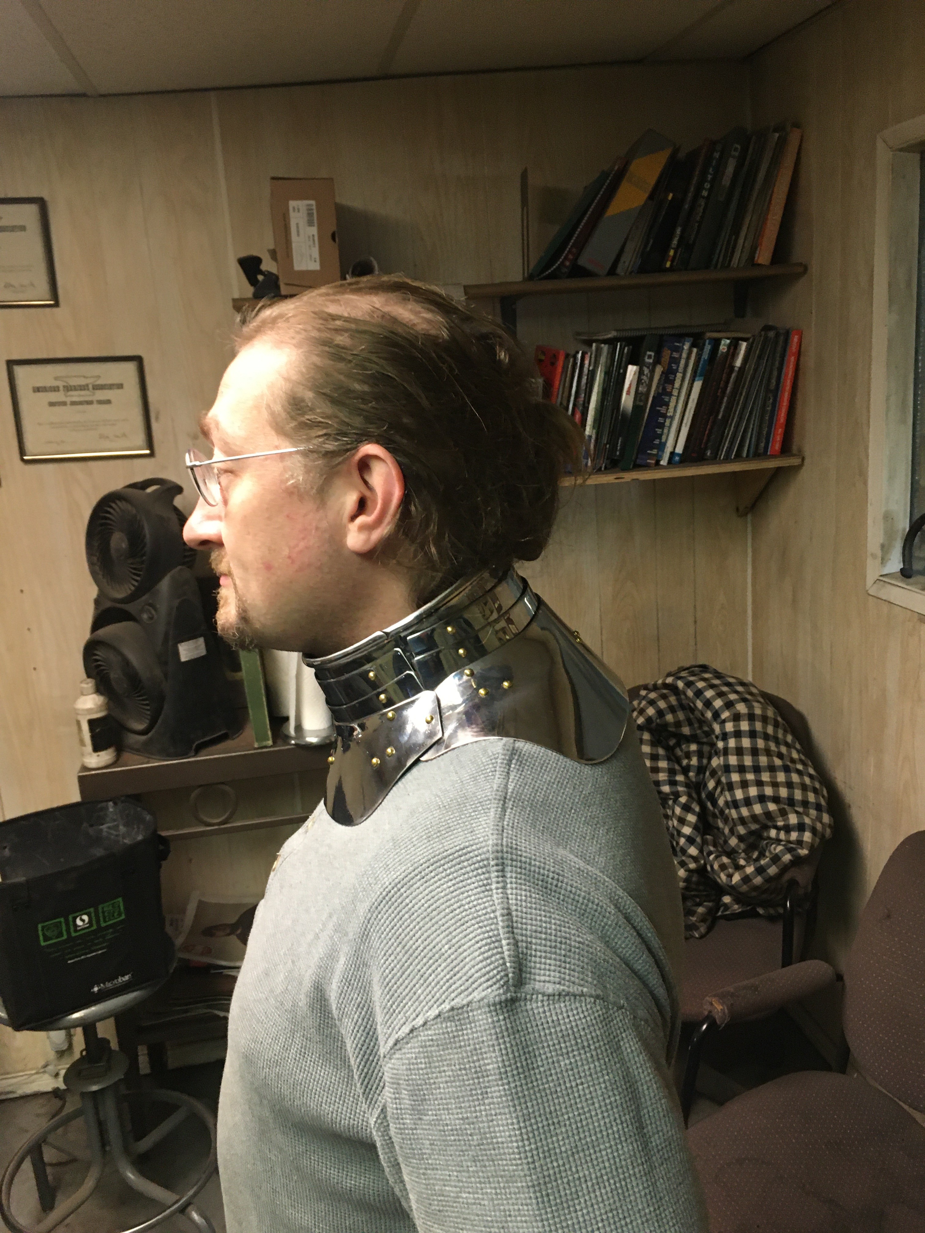
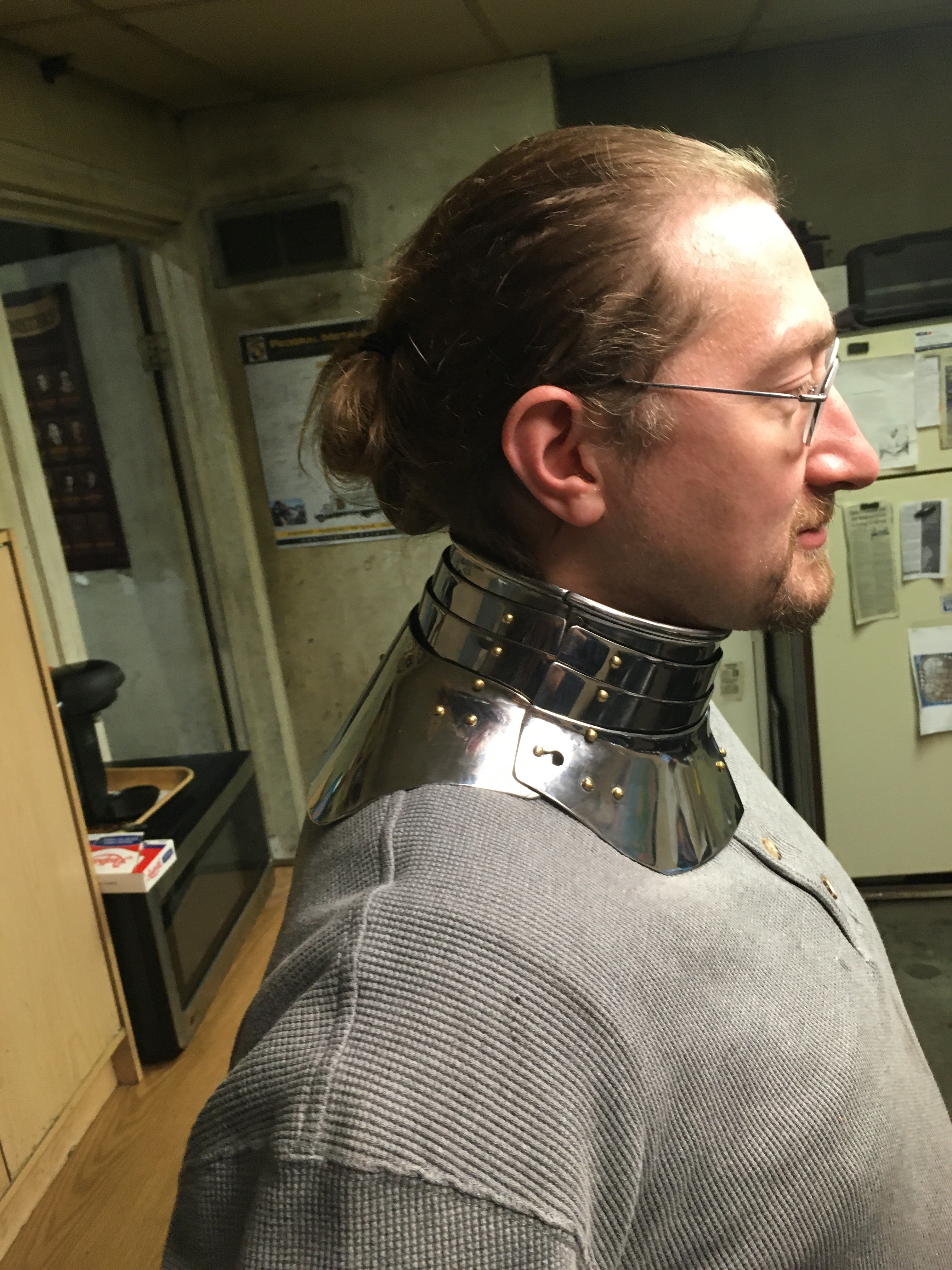
Here’s a few pictures of the completed piece – thanks to Dean for modelling:
Overall construction methodology
Here is a build thread on the Armour archive where John Cope and I (in parallel) tried to reproduce this gorget.
The last time I built one of these, I used very thin stainless steel and the collar roll was minimal, with a 1/16″ copper wire rolled in. The actual gorget is a “jelly roll” of material sufficient to engage a helmet (probably a close helm, possibly an armet) so it needs a fairly substantial roll to engage this. John Cope did the “jelly roll” and it took him a considerable amount of time and a lot of working hot to accomplish it. For this attempt I am working in 0.050″ (18 gauge) carbon steel for the upper section and 0.625″ (16 gauge) for the front main plate. The steel used is 1050, which has slightly too much carbon for the use (medieval carbon steels of this period centered around 1040) but is still fairly close to the medieval material. To get a thicker neck roll I am tucking a 1/8″ welding rod into the roll, which was a bit more involved that I was expecting, but seems to have worked out. Since I have now done this “roll” in a number of ways, I have settled on doing the hinge after the roll is complete and the plates are rounded (discussion below). In general I find that starting from the “inside” of a piece and working out is the easiest way to proceed, so the overall construction methodology will follow that approach. Note that in the list below, the bolded sections are a considerable part of the work, with the work being roughly broken between the top neck plate (with roll and hinge), shaping the back plate with its’ deceptively challenging anticlastic curves, and “all the rest” being the remaining third of the work. The overall construction methodology will thus be:
- Cutting the components
- Building the top neck plate
- Building the remaining neck plates
- Rough shaping of the back plate
- Rough shaping of the front plate
- Blending the components
- Building the top catch
- Installing the leathers
- Building the lower pivot and catch
I will not go into detail on cutting the components: I use a beverly shear to cut the pieces, and then flatten with a hammer on an anvil and deburr (clean up the sharp edges) with an autobody sander with 240 grit sandpaper. If you don’t have a sander, you may want to look into a “deburring wheel” for a grinder, since these are very soft / fine wheels that will not accidentally take a “bite” out of your work. The pattern (PDF) is linked below and includes the neck pattern (which is a big rectangle) for completeness.
Pattern Link for 1560’s Ausberg Gorget
Building the top neck plate
Overview of the top neck plate
As noted above, this part of the project is responsible for roughly 1/3 of the total effort in the piece, so expect that if you have done lots of armour before this will take a full day – more if you don’t have that experience.
For the top “ring” there are a number of interacting details that need to be remembered.
-
- The roll must be an outside roll, so the outside of the piece will not have a visible seam
- The front overlaps the back, and the roll is cut at a 30-45 degree angle to eliminate any seams that could be exploited
- the hinge is designed to open just enough to get your neck in, so the hinge joints are beveled – note that this means that if properly constructed, you cannot see daylight through the hinge
- As a result of the bevels, the back “roll” passes over the hinge, with an asymmetric joint on the hinge side
- On the non-hinge (catch) side the catch is positioned such that the catch is forward of the seam line – so the back plate must underlap forward of the centerline. this allows all of the lames to be in alignment with the seam joint in the upper ring
I’ll go into detail on these below (with pictures) but it means that when you are building this piece the top ring is asymmetric. On the hinge side the back will have an extra length of roll, while the front plate will have a gap for this roll to about 1/4″ – 1/2″ past the hinge location. On the catch side the front plate will define the line of articulation, and the back will need a “tab” to project forward roughly 1/2″ past the line of the roll. Knowing this ahead of construction (instead of fiddling around and THEN noticing it) will make your life much easier. Here are some reference photos to the original piece:
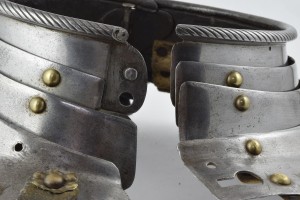
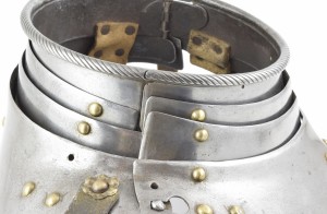
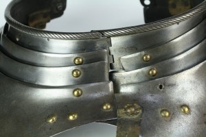
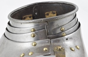
Photos of the insides are also quite instructive:
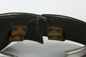
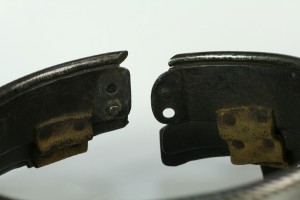
Note that all of these links are back to the original main page, clicking through there will provide high definition photos – including some additional photos that I requested to help in my construction (thanks Wade!)
For the roll, I started by running the flat sheet (24″ long x 2″ wide) through a bead roller to set a consistent start to the work. I have found that I get better results with shorter pieces, so the next generation version I used 2 pieces a bit over 12″ in length. Note that having extra length means you can trim it down at the end, but not having enough means that you get to redo the roll. This was important for my first piece, because I did the hinge on the wrong side which was a lot of wasted effort, and would have required me to build a new piece if I didn’t have the extra length.
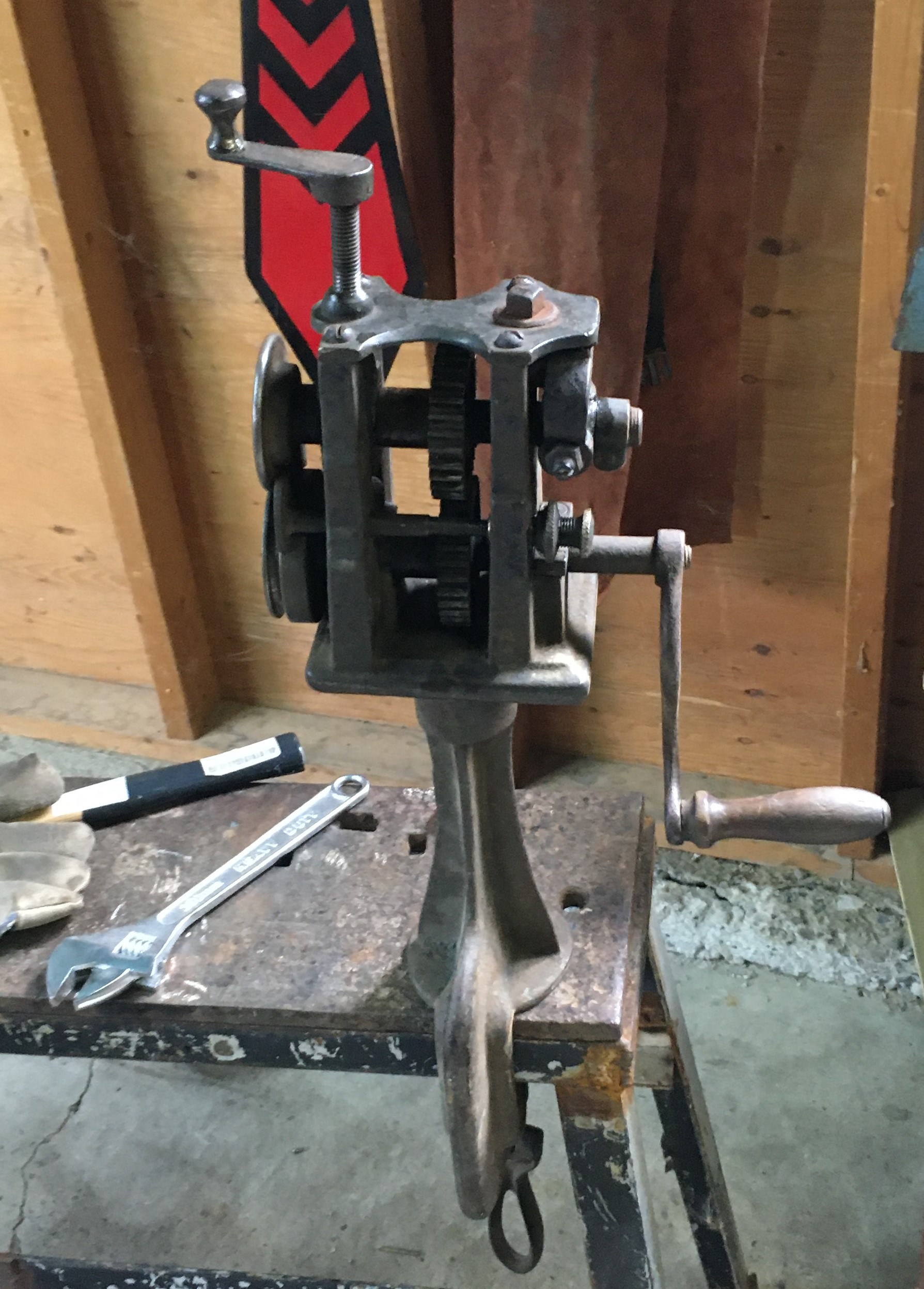
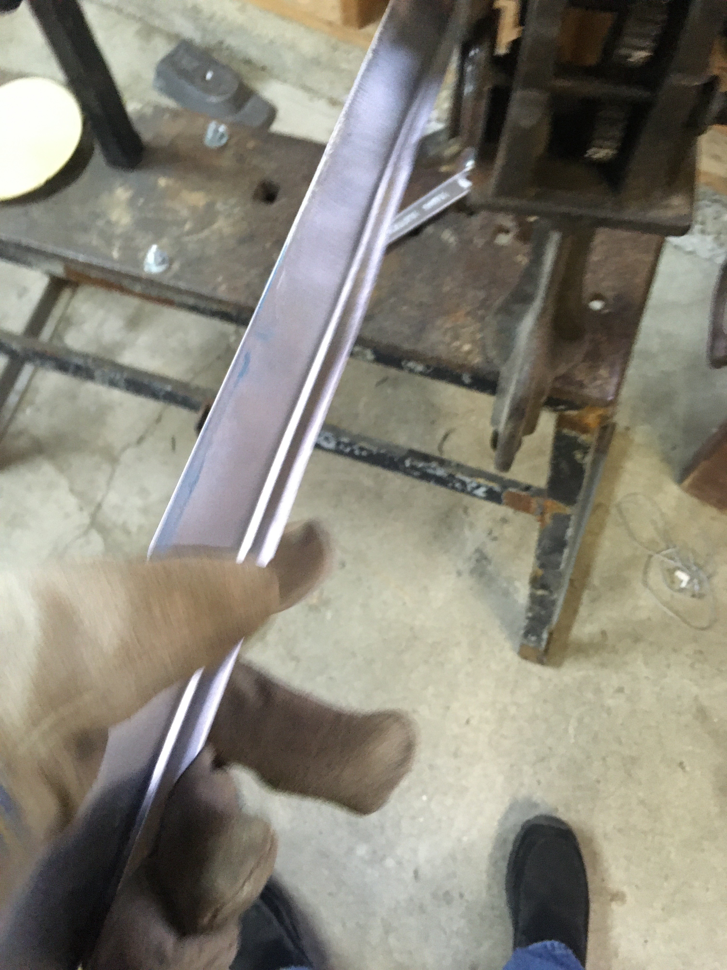
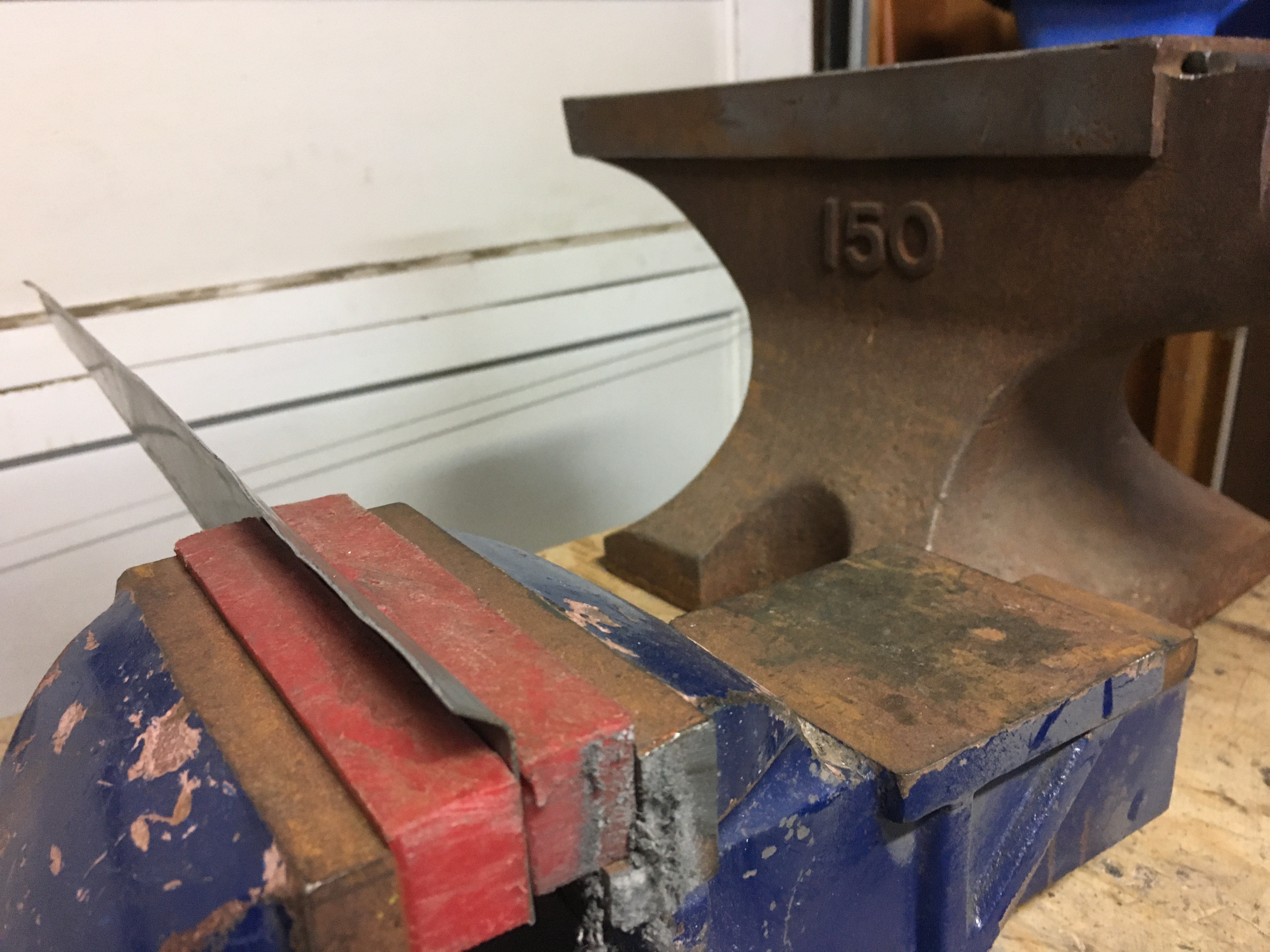
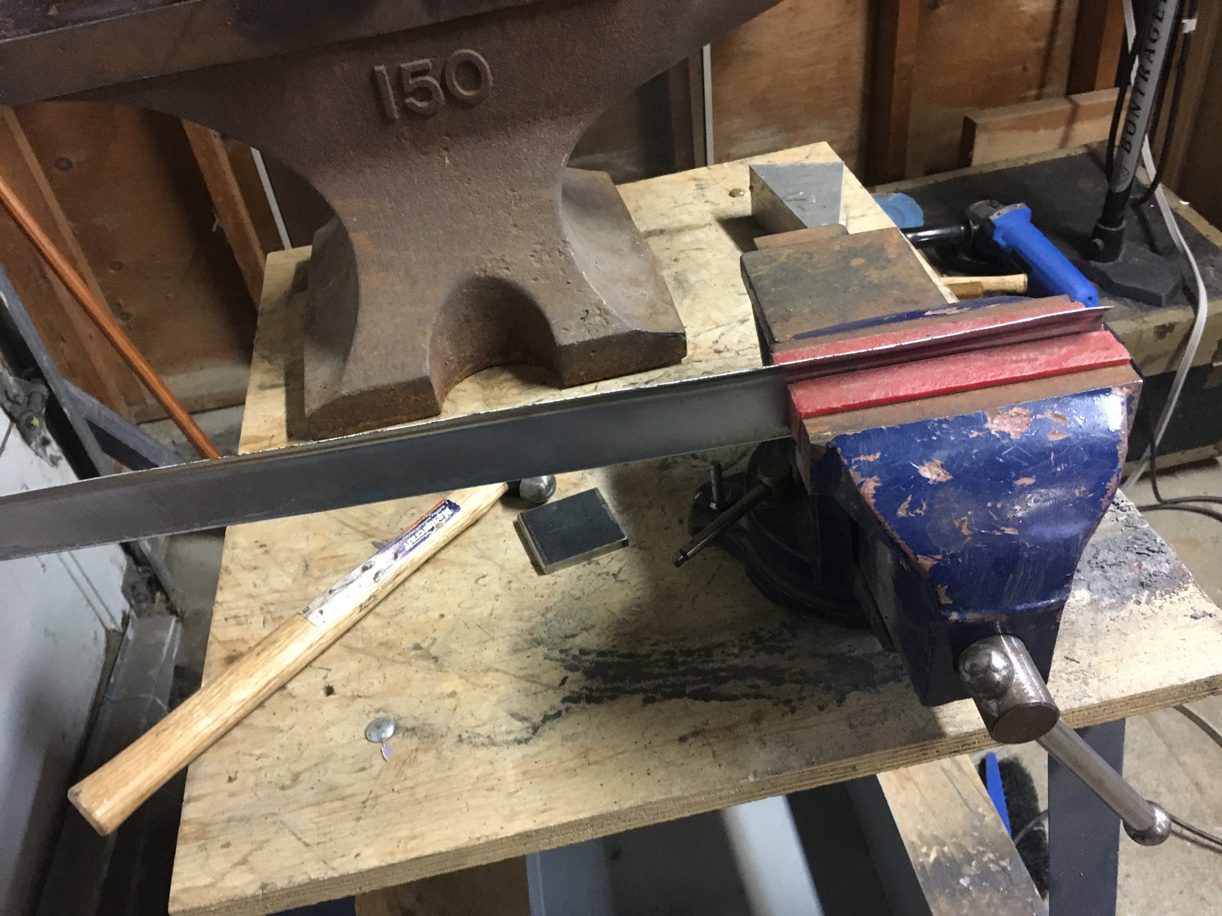
I used the bead roller for 2 reasons: the first is that it takes about 5 minutes to run a piece through the roller, and completes about 45 degrees of the roll. It also gives a bit of an offset or “push” out of the plane of the material (which I want for the outside roll) with the edge of this bead at roughly 1/2″ from the edge of the plate. For the completed version (shown above) I trimmed 1/4″ off this piece later, and then realized that for the second lamination to cover the locking mechanism the plate needed to be 1/4″ taller. For the version I am currently working on, I did not trim this, and it looks like I will have the correct amount of material (and the gorget will be 1/4″ taller overall). Regardless I would recommend “wasting” that 1/4″ since it’s easy to trim a little extra, but it is very hard to add an extra 1/8″ if you need it later. The roll itself uses slightly less than 1/2″ of this depth, and for my first attempt left a bit of void space in the roll. The current version I was very careful about tightening the roll. I then moved to my soft-jawed vice to push the roll over to about 135 degrees, which took another two passes. When I am doing a roll, I generally use a small (8 oz) domed hammer and make a lot of small overlapping strikes, so that the edge does not get at all “wavy”, as can be seen in the following photos:
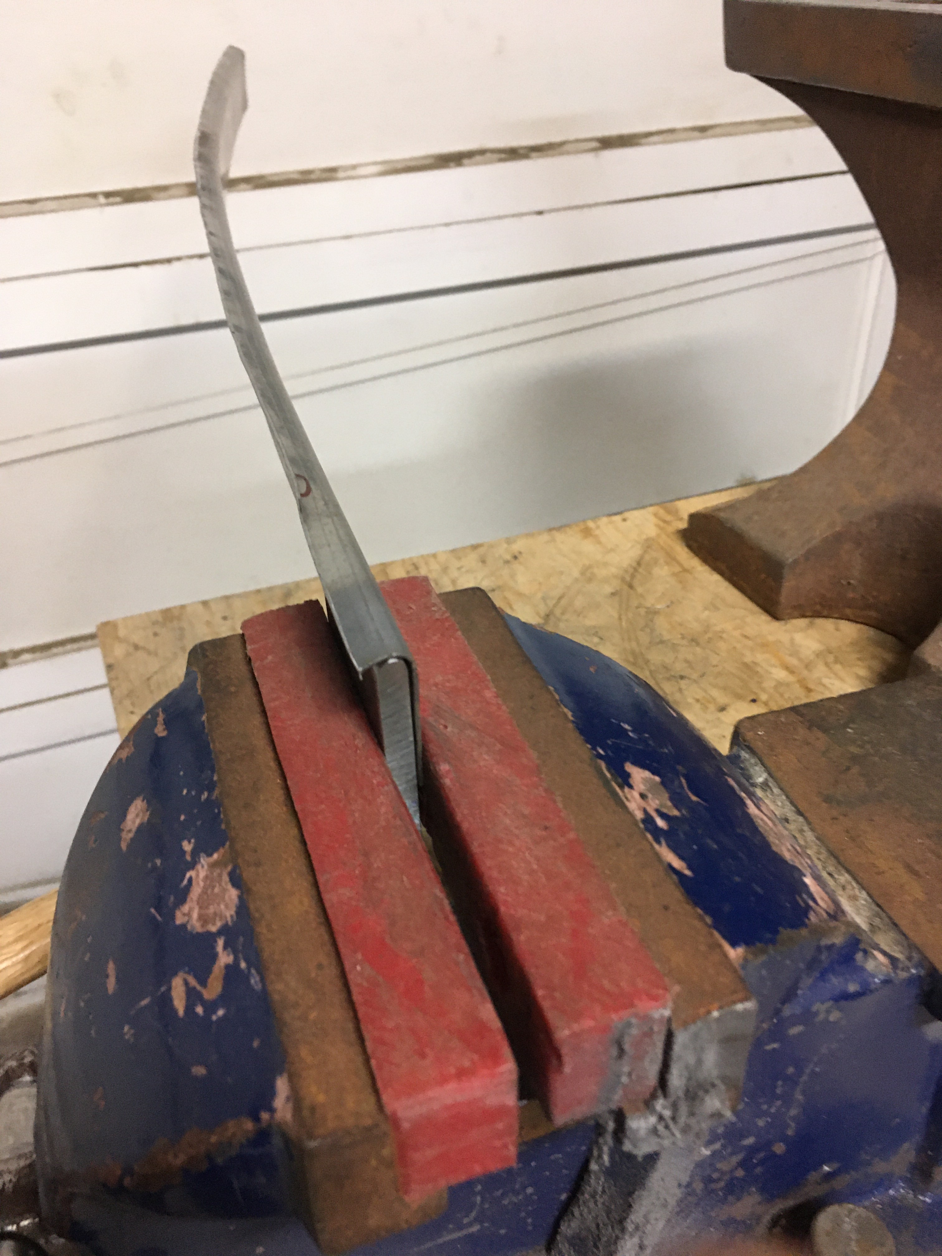
Once this was rolled to about 135 degrees it was time to close the roll. While it is faster to do this closure on a solid surface (like an anvil face) if you make a mistake it will be on your piece forever, so I tend to do this into a wood stump, with slow even passes until I have just enough room to fit the reinforcing rod in. Note that the original used a “jelly roll”, rolling the metal roughly 2 1/2 times to get the thickness of the roll. This would have avoided rod slippage which I experienced (below) but is a significant amount more work.

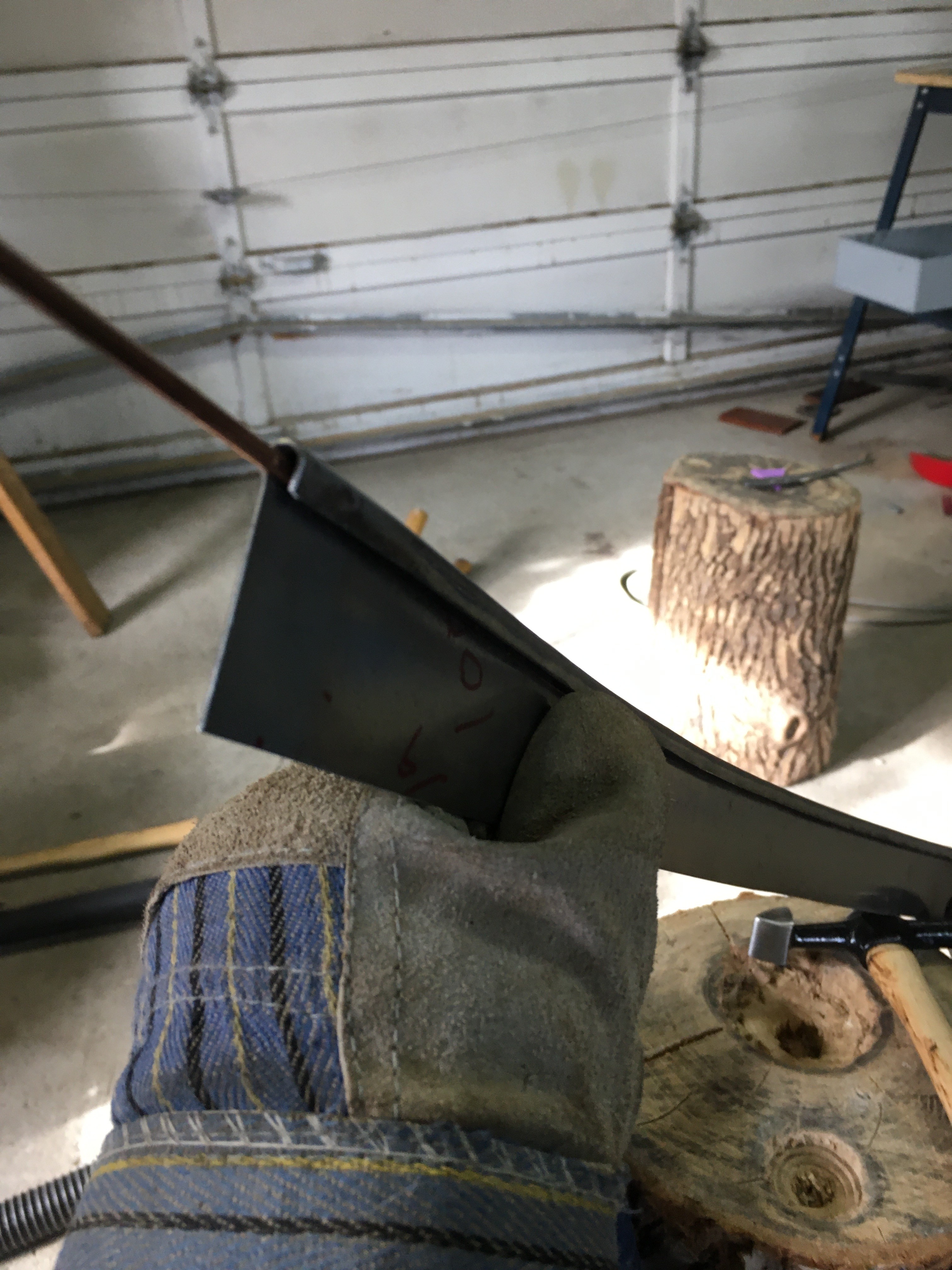
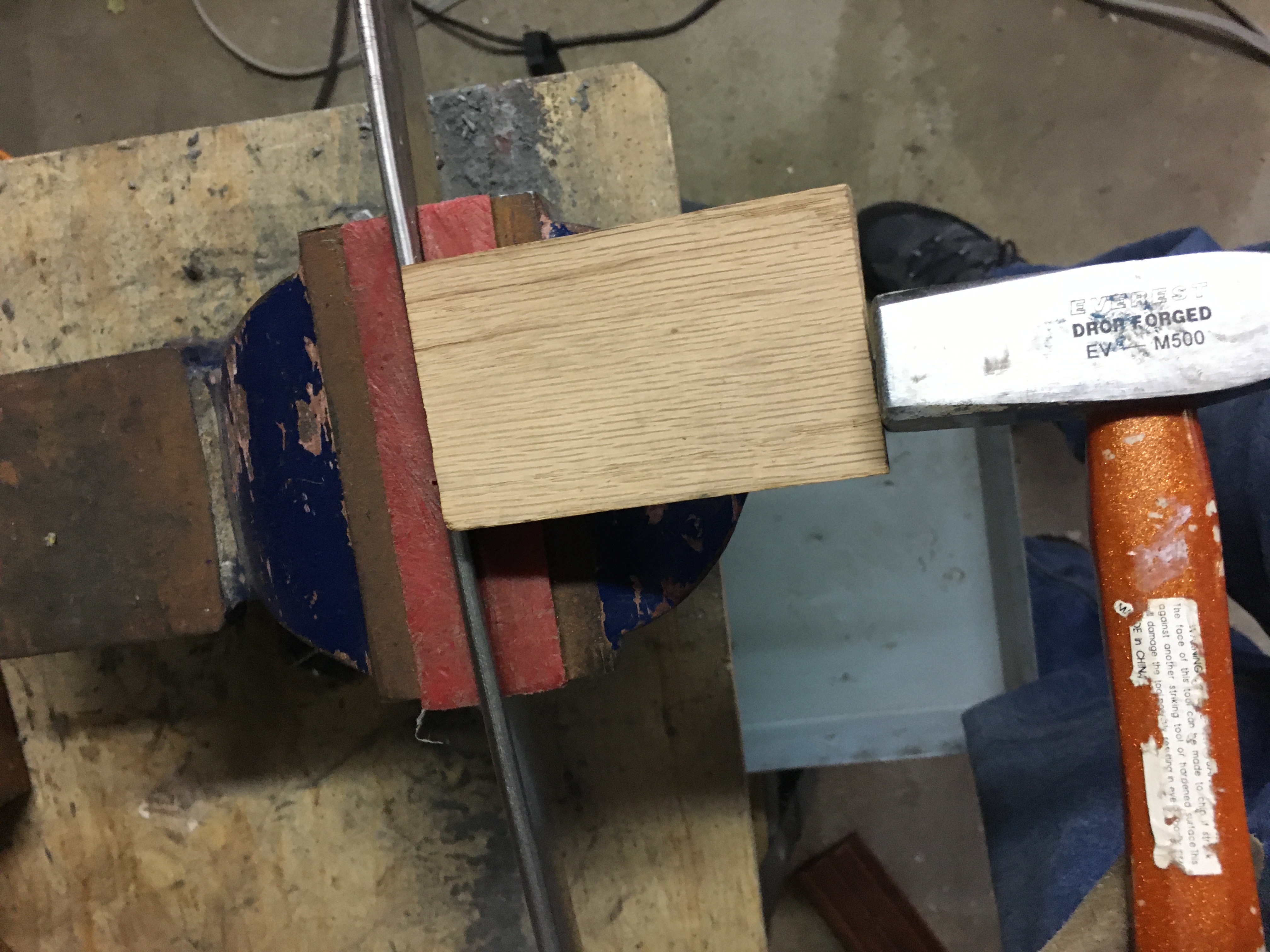
Once the roll was closed, I needed to “push” the roll to the outside. While this would happen of its own accord while shaping the piece, I find it easier to control if this is done first, particularly if the gorget is meant to engage a helm, requiring as much symmetry as possible. To do this I secured it in my soft jawed vice and used a iece of hardwood (oak) as a striker, striking it with a large (2 to 4 lb) hammer.
For the gorget lames and lower plate, there are a number of considerations to include, which will make construction easier
-
- the front lames line up exactly on the seam line
- The back underlaps the front plates, but this is a very small (1/2″ at most) overlap. This is possible because the top ring is a hard articulation and is always with a millimeter of position, and the bottom plates (that will interact with the cuirass) are also hard articulations and will remain within 1 mm when closed.
- The bottom plates are again the front over the back, with a slotted pivot rivet on the left and a locking (keyhole) closure on the right
- the easiest way to get the slot correct for the “hinge” side is to punch the hole for the pivot, and open the gorget while poking a sharpie through the hole. This will draw a curved line that describes the opening
- a similar approach can be used on the closure side, with the BACK plate being punched first, and drawing the arc on the front plate (on the inside)
- punch the “closed” position first for the closure, then use a larger punch for the “openng” position (the farther forward one) – you may be able to simply file out the channel if you use this approach.